Mohr’s circle: Construction
Use the solutionAppletFlashanswer type to create Mohr's circle construction items. Mohr’s circle is a two-dimensional graphical representation of the state of stress at a point. The Mohr’s circle construction authoring feature lets you build an item Part that asks students to build either a:
- Mohr’s circle for plane stress
- Mohr’s circle for plane strain
Students construct the circle in a multi-step process. The answer is graded as correct as long as the center and reference points are correct.
Requirements
To work with the Mohr’s circle construction authoring feature, you need the Adobe® Flash® Player.
To create a Mohr’s circle construction question:
In the Item Editor window
- Select Edit in Browser from the Edit Action menu in the upper right.
- Remove the default item.
- Under Answer Instructions, select solutionAppletFlash.
- In the input fields, add the following:
- For Applet Name, enter mohrs_circle.swf
- For Parameters, enter authoring=1&analysis=0.
- Set Width to 1000 and Height to 500.
- Click Validate Field and then Preview Item.
You will see the applet in authoring mode.
In the Item View window
- Initial plot location: Click Initial Plot Location at the top left of the graph to position the origin. For example, position the origin towards the center if you want students to see it at the center of the graph. Position the origin towards the right if you want students to see the origin towards the right.
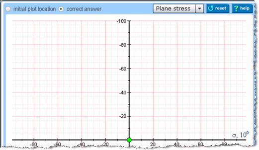
- Correct answer: Click Correct Answer at the top left of the graph to plot the correct answer.
- Plane stress or plane strain: Choose one of these options from the dropdown menu above the graph area, depending whether you are working on Mohr’s circle for plane stress or plane strain.
- Diagram Settings and Element Settings

- Using the Diagram Settings and Element Settings controls on the right, set the axis.
- After you set the axis, click on the graph to plot center point C.
- Click again to plot reference point A.
You can continue to adjust the locations of A and C. Plotting points A and C constitutes the correct answer. Radius is automatically calculated.
- Tolerance settings: Click Answer Editor on the top right. Below the Mohr’s circle, adjust the unit values for the coordinate tolerance and radius tolerance.

- Wrong answers: Click Add in the Wrong Answer area.
You will see a number of checkboxes on the left for wrong answer conditions.
Click in checkboxes to indicate applicable conditions for the wrong answer ID. The available operators in the dropdown menus are: > (greater than), < (less than), = (equal to) or ≠ (not equal to). Click Add to create remaining wrong answer conditions.
Use the available icons to work with your list of wrong answer conditions.
 = Move up through list of wrong answer conditions
 = Move down through list of wrong answer conditions
 = Edit
 = Delete
 = Copy
 - In the Altova editor, enter the wrong answer IDs under "Value" and enter wrong answer responses under "Response".
- Click Save to save the configuration file to your desktop. Then upload it, by selecting Manage Assets from the Edit Action menu.
A window appears with the answerString and flashVars strings.
The configuration file contains information about the correct answer and the wrong answer.
If you ever change the correct answer or the wrong answer, you should save and upload the file again. The wrong answer response you write in the Altova editor next to each wrong answer ID is independent of the configuration file, but the wrong answer itself needs to go into the configuration file.
- Copy and paste the answerString string into the Correct Answer(s) field, then copy and paste the flashVars string into the Parameters field. Click OK.
- Before you commit your changes:
- Change the authoring parameter from 1 to 0 to switch to student view.
- Adjust the size to 600 by 600, so that the workspace will be a more manageable size.
What the student sees
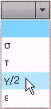
- Students are instructed to use the dropdown options to label the relevant axes with σ, τ, γ/2, or ε.
If a student chooses an incorrect convention for plane stress (or plane strain), the student doesn’t lose any credit and the following message displays.
- Horizontal axis represents normal stress (or strain) with positive to the right.
- Vertical represents shear stress (or strain) with positive downwards
- Next, students are asked to mark the center (C) of the circle by clicking on the graph.
The default position of the center of the x/y axis is in the center of the graph. Students are given instructions to let them know that they can move the center any time before clicking Submit, and that they can position the origin anywhere on the screen to fit the circle.
Tip: Although authors can redefine the default position of the center of the x/y axis from the center, it is recommended that you do not change this. Students can move the graph around to accommodate the circle on the screen. Students cannot make any changes to the axis. The author should specify the interval points and other information for the axis.
- Students need to mark the reference point A.
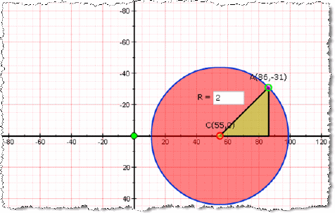
Once a student indicates reference point A, a right-angle triangle is drawn on the graph. Students see the following instructions.
"Reference point A represents the normal and shear stress components on the element’s right hand vertical face. Plot it by clicking on the graph. You can move it around and adjust the position any time before you click "Submit"."
- Students determine the radius value (R) of the circle.
An instructional message says: "Point A and center C are connected for you to determine CA by trigonometry."
- Students click Draw Circle.
Whatever value the student has entered for R, a Mohr’s circle will display on the graph with center C and reference A lying on the circumference.
- [Optional] Students can change the position of C, A, R and click Draw Circle to reposition the Mohr’s circle.
- When students finish their work, they can click Submit.